Re: "Radiopunk" // In Which Teague Uses This Forum As A Notebook
There's a handful of different ways you can build a circuit at home; the whole point is to grid out some conductivity in a pattern that suits your needs, so it's a fairly flexible process.
In the old days you'd just take a piece of wood you had lying around — traditionally a cutting board from the kitchen — hammer in some nails that would act like little telephone poles, and string wires between the nails. We've moved on, but we kept the terminology; a surface for prototyping circuits is called a "breadboard." The plastic breadboards we use today are a sensible pattern of temporary slots meant for jamming wires into, so you're free to change your mind for the rest of your life and never deal with the troublesome fallout of choices or soldering.
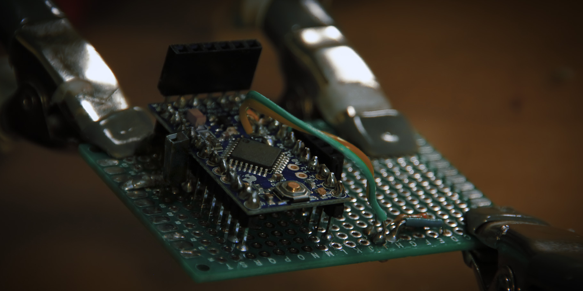
There's no law in electronics that says you can't use a breadboard as your permanent circuit (which is odd, because there are laws in electronics for pretty much everything else), but a solderless breadboard is a fairly chunky and impermanent block of plastic. Perfboard, on the other hand, is a sleek sheet of god-knows-what that comes with a grid of holes perforated into it. Thread your components through the little holes, solder them to the provided copper pads, trim the excess wire; you're left with a poky field of silver Hershey's Kisses on one side, and a beautiful circuit on the other.
There are levels of complexity and coolness beyond this, too, but they aren't a part of this particular story. Suffice it to say, if you don't mind messing with a tub of crazy chemical liquid and finding something to keep the air ventilated, you can actually etch your own circuit boards with copper traces squiggled out exactly where you need your wires to be, and all that's left to do is drill holes into those traces and poke your components through them. Those boards usually end up looking enviably cool.
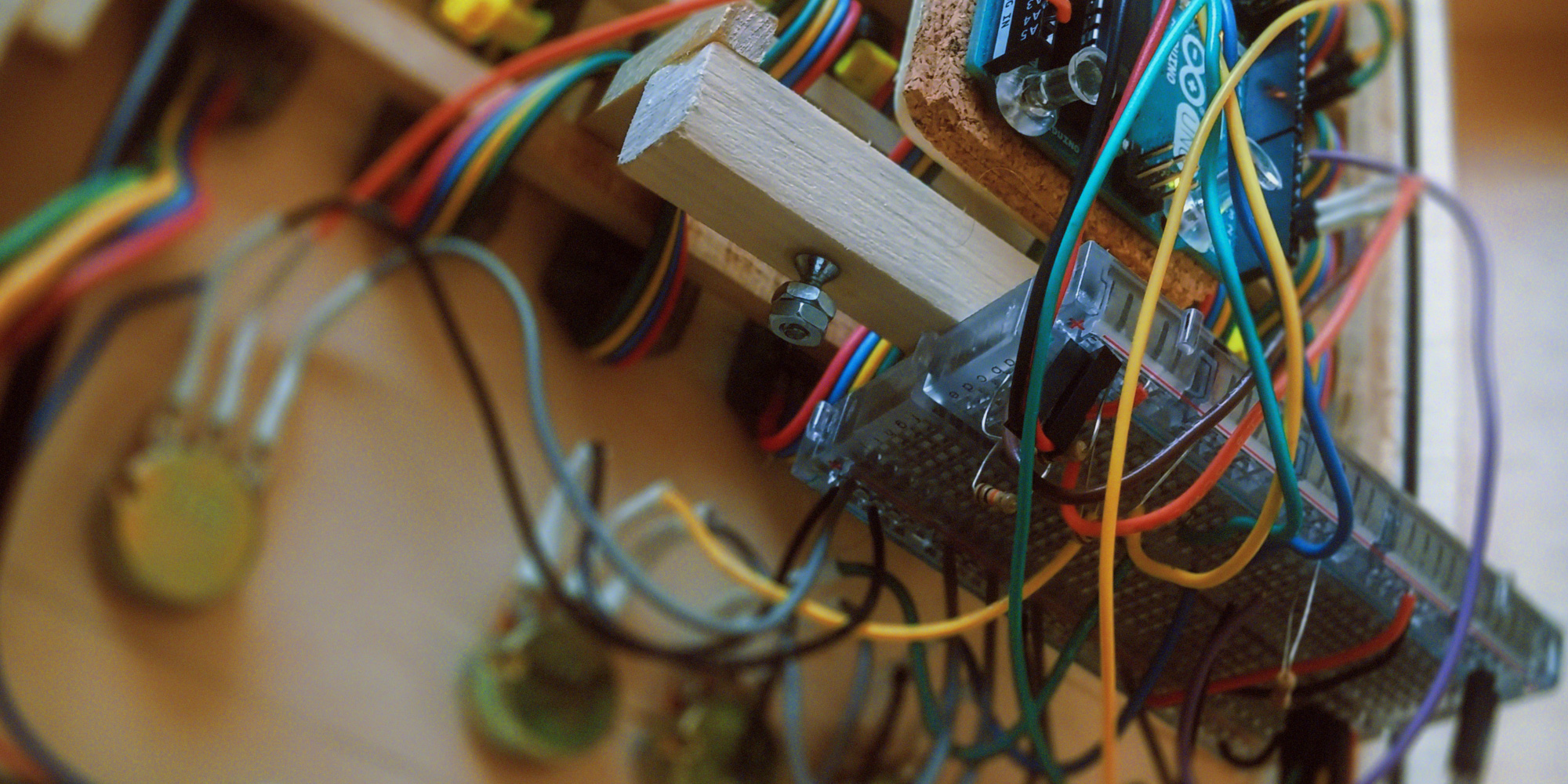
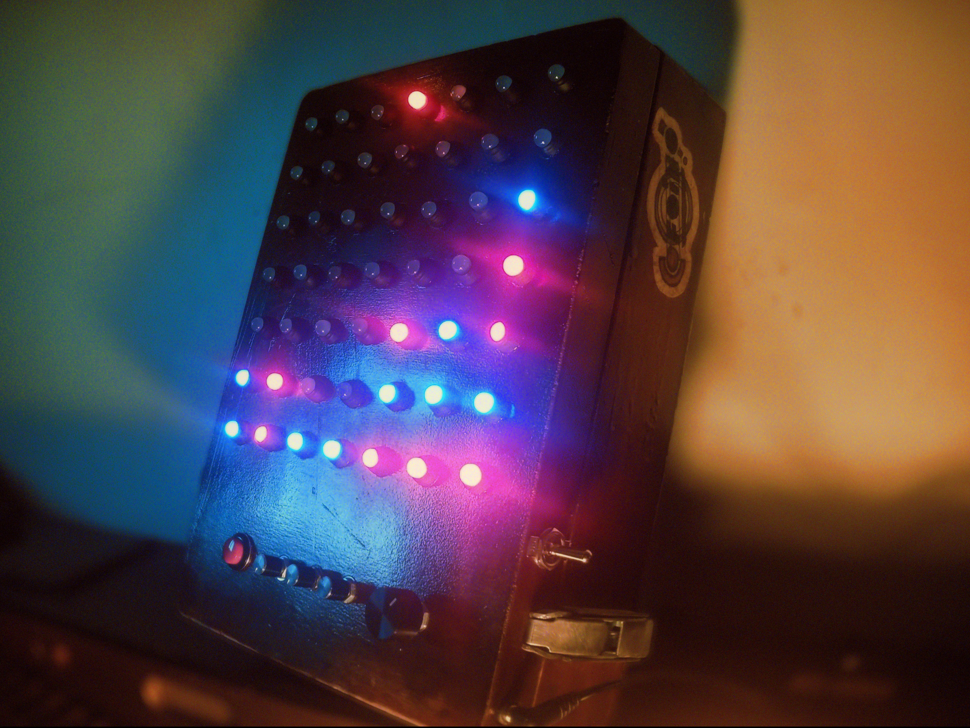
In the case of the CoFoiNo, I built eight or ten various prototypes at different stages along the way, and "prototype" carries a fairly loose definition here. The early "prototypes" were things like the two-piece rig I used to turn on the lights for the first time, just a wire going into a thing; later attempts would be more complex. The picture above shows a pretty rugged prototype, it lasted for weeks; just a simple breadboard-based junction point between all the wires coming off the control surfaces and all the wires getting routed into the Arduino. This was my circuit during the whole, "write some code, see if it works, figure out why it doesn't, repeat" stage of the project, and it's pretty close to the "real" circuit that would ultimately come — with one major exception. When your project is living with an umbilical USB cable, your power is handled for you. Once you're done coding and ready to go out into the big world, you'll need to wrangle your own electrons — and for that, you'll need knowledge.
Complementary knowledge provided below.
Solder is a friendly wire made from metals with a low melting-point. You can unwind a bit of solder, push it onto another metal surface, and use a very hot stick to "flow" melted solder onto the metal. One second later the solder cools and solidifies, leaving a permanent conductive bridge between it and the surface it's on. It's tempting to think of solder in terms of glue, and for all practical considerations that's fair, but where glue merely "holds" a couple of surfaces together, solder becomes molecularly entangled with those surfaces. In fact, as far as electrons are concerned, you've just made one piece of metal out of two — or three, or fifty, or whatever — and this one trick contains all of electronics. You start your electronics build with a bunch of pieces of metal, in the form of wires and components, and you eventually convince electrons that they're all one big piece of metal.
(I'm leaving out some important concepts, by the way. Non-metal semiconductors, electron flow, etc..)
(Actually, just consider this entire explanation a poem. The physics are not actually like this.)
As far as the electrons know, they're exercising free will about which parts they'll go through, based on areas they prefer more than others. This is because electrons don't know about resistors; they look at an area of resistance, groan, and say, "is there another way to the far side of this thing?" If there's not, they'll trudge through the resistor and snap out the other side. If there is — and there's not supposed to be — that's a short circuit, and a swarm of disloyal electrons will nope out of your whole intricate series of reductions and take a shortcut right to the end. The problem with this is that the circuit was expecting you to engage in some basic crowd control, and now it's like The Who are playing tonight.
I apologize for reducing "people being crushed at a The Who concert" to a symbol, but... actually, it presents a morbid alternative to the usual 'flow of water' analogy for electricity. Let's think about it in terms of crowd control and throngs of people; our total available power coming out of the outlet will be the crowd at Disneyland — picture the crowd, picture a deafening mob of insane tourists in mouse-ear caps, all of them desperate for thrills, they're savages — and our little Arduino project will be the maximum occupancy of a boat on the Pinocchio ride. (It's a ride where like ten people get on a boat and are gently floated through a park decorated with miniature houses and stuff. It's the thrill-equivalent of a chinchilla thinking about a hug.) We have to divert enough members of the insatiable horde onto Pinocchio that there's always riders, but not so many that the scene devolves into a nightmare.
In this analogy, "how many people are entering the line" becomes "amps," and "how completely overcome by ravenous insanity they are" becomes "volts." Both numbers are obviously important, and they're important in slightly different ways: if it's not too much of a crowd, we should be okay; if they're not too insane, we should be okay. Just gotta keep keep the crowd and the sanity at the right level.
Resistance is the difficulty of a surmountable obstacle; it's also the third player in Ohm's Law, which states "voltage equals amperage times resistance." In real life, that means you can trade amperage for voltage by adding resistance. In our analogy, that means an unpleasant obstruction in the line — say, a frat guy who snuck alcohol into the park and is now vomiting on people's shoes — will diminish the number of people who stay in line, which is good, but the people who stayed will have been driven much more insane in the process.
Patience diminished. Desperation increased. Voltage rising.
The idea is to control the flow of people onto boats, and there's two ways they can get past you: a large-enough group cramming into the line (cough The Who cough) will just trample you and swamp the boat, or, an insane-enough group will just murder you because they want the hell out of that boat ride. We fail in either case — we fail if there's eleven passengers on the boat, or if there's two passengers on the boat and they're both trying to convince the other that they're Jesus.
That's electricity in a nutshell; avoiding catastrophic crowd behavior. Amps is the headcount, volts is how insane and determined they are, resistance is how you trade a big calm group for a smaller insane one.
With that in mind, let me give you a couple figures and show you a schematic. The socket in my North American wall is putting out around 120 volts — it's spewing determination, pretty much — and for our purposes, we can safely pretend there's infinite amperage.* The Arduino will want between 9 and 12 volts and at least a quarter of an amp, and the Neopixels have to be considered separately because they'll want exactly 5 volts and they're definitely gonna need an amp or two. We want to run them off of one adapter, so we'll need to accommodate the bigger numbers — find an adapter that puts out 12 volts, rated for loads up to 2 amps — and then manually split off a lower voltage for the Neopixels somewhere inside the circuit.
* Despite the crowd-trampling analogy, amps are generally something your device pulls rather than is-pushed-by. (Volts push, though.) To phrase it in terms of the analogy, tramplings are very rare and insane people are a constant problem. Actually, that's probably just true in general.
We'll come back to the special-needs dual-voltage power supply issue later, because that's a whole separate conversation; for now let's pretend like it doesn't exist. Let's pretend that we're actually surprise heirs to a forgotten family fortune, and that our bed will be full of puppies tonight, and that an Arduino and a bunch of Neopixels can share a power supply. Reality thusly suspended, take a look at this schematic.
This is what the Pinocchio ride looks like.
That's our power supply, in the top left. (Entrance to the line.) The schematic symbol for a DC power supply is a few pairs of vertical lines with a taller line and a shorter line in each pair; thus the symbol has a tall line on one side and a short line on the other, with the tall side being positive and the short side being negative-slash-ground. (Ground would be the far end of the ride, where people get off having gotten what they came for.) The symbol for ground is a vertical line dropping into a horizontal line and dissipating, which represents... the... ground, I'm guessing. Art. Whatever.
You can see that there is one big blue ground being shared throughout the entire project — this is true of all circuits, you always want everything to share a common ground. You can think of it in terms of a gutter; you're adjusting power all over the place, and after every adjustment it's either getting read by another part of the circuit or going into the gutter. I've left out "return" arrows coming back up the ground wire to the power supply, but you could picture it that way if you wanted to. You can also see the big red line — which is our power, call it 12 volts coming out of a "brick"-style wall adapter — and the first thing that happens to it, which is that it arrives at the giant comedy-sized toggle switch.
The symbol for a switch is pretty sensible, it looks a wire with a door swinging out of it; the idea being, close the door, close the switch, close the circuit — connect the wire. When the toggle switch is open, the actual physical connection inside the switch is broken, the wires are separated by air and the power doesn't go anywhere. (Another way of thinking of it is that the air has infinite resistance, which could be an infinite number of vomiting frat guys holding up the line, or, like, a sign that says "go away.") When the switch is connected, the power moves on through the circuit.
The Arduino and the Neopixels are both getting their power straight from the source, in the form of the solid red line. The Arduino uses some of that power to do its Arduino-ing, of course, and the rest to power the peripherals it's attached to. What's nice about this is that once you've powered an Arduino, at somewhere between 9 and 12 volts, the Arduino will turn around and provide you with a safe 5-volt source — represented by a dotted orange line in the schematic — that you can use for measuring the throughput of knobs and buttons and whatever other voltage-measurement devices you're using, and you can be assured that you're not gonna blow the Arduino out of the water with more voltage than it can handle.
With the nice 5-volt power source from the Arduino, we set up a couple of "rails" — that is, an open canal of power, an open gutter of ground — and just tap into them for our control surfaces as necessary. This amounts to a parallel circuit, where every little device is drawing from the same big pipe as equals, instead of one device getting first dibs on the power and passing along the leftovers.
The CoFoiNo has five controls; four knobs ("that's potentiometer to you, kid") and a button ("momentary push-button switch, please, I didn't go to school for eight years to be called a 'button'"). You'll recognize the symbol for the button as being the same symbol we used for the toggle switch; the symbol for a potentiometer is actually the same symbol you'd use for a resistor — wire going into one side of a box and out the other — with an extra slant-y line on top of it, to indicate that it's variable. As far as our circuit here is concerned, the button and knobs are all almost exactly the same thing: power goes in one side, is adjusted by the user, and delivered to the Arduino in a thusly-chosen state. The button is an all-the-way-on or all-the-way-off signal that comes in at 5 volts; the four knobs all return a variable voltage between 5 volts and 0 volts depending on how twisted they are.
(Heh — "twisted." Synonym of "insane." The system works, people!)
Arduino provides some power, power goes into the button, power is sent back to the Arduino by pushing the button. The Arduino is measuring the button voltage digitally, which is to say it's only accepting "on" or "off" answers on the button front. The power also goes into the knobs, whereupon some amount of it is getting shaved off and immediately sent to ground, and the remainder is sent back to the Arduino. The Arduino is measuring the knob voltage analog-ly, which is Arduino-ese for "instead of two states, 'on' or 'off,' we'll say there's 1,024 states of 'on-ness' to 'off-ness' and round to the nearest one." It's comparing the voltage coming in — 2.5 volts? 0.8 volts? 4.6 volts? — to the voltage that it provides — 5 volts — and taking note of the fraction.
Once the Arduino has that information — is the button being pressed? how much red-green-and-blue is the user asking for? where does the user want the selected column to be? — it can fill in the variables in the Connect Four program, so it's ready to go. (It's worth mentioning that we only need to know the R-G-B knob values during the "pick a color" stage, so those particular variables spend a lot of time not-mattering.) The program does its clever work of taking the user inputs and re-arranging them into a meaningful series of grid-based pixel commands, and it sends those commands into the Neopixels.
The user inputs are all handled by the Arduino reading incoming voltages; the Neopixel commands are all sent by the Arduino writing voltages. We don't actually have to know how that happens for us to program it — the specific digital voltage timing that tells the Neopixels what to do is all handled by a software library that was written for use with Neopixels, so we can just say "pixel 5, red 255, green 0, blue 0" or whatever and the library converts that into a series of impossibly-fast voltage pulses that the Neopixels understand — all we have to do is hook up the last two Neopixel wires to the Arduino.
And, guess what?
You flip the toggle switch and the game works.
In theory, anyway.
Can Teague stretch the rogue wave cliffhanger past its breaking point?
Will we get to see the actual circuit on an actual board?
Is this going to be the longest document ever written?
Stay tuned
I have a tendency to fix your typos.


