Re: "Radiopunk" // In Which Teague Uses This Forum As A Notebook

There's a handful of different ways you can build a circuit at home; the whole point is to grid out some conductivity in a pattern that suits your needs, so it's a fairly flexible process.

In the old days you'd just take a piece of wood you had lying around — traditionally a cutting board from the kitchen — hammer in some nails that would act like little telephone poles, and string wires between the nails. We've moved on, but we kept the terminology; a surface for prototyping circuits is called a "breadboard." The plastic breadboards we use today are a sensible pattern of temporary slots meant for jamming wires into, so you're free to change your mind for the rest of your life and never deal with the troublesome fallout of choices or soldering.


http://www.friendsinyourhead.com/arduino/030.jpg


There's no law in electronics that says you can't use a breadboard as your permanent circuit (which is odd, because there are laws in electronics for pretty much everything else), but a solderless breadboard is a fairly chunky and impermanent block of plastic. Perfboard, on the other hand, is a sleek sheet of god-knows-what that comes with a grid of holes perforated into it. Thread your components through the little holes, solder them to the provided copper pads, trim the excess wire; you're left with a poky field of silver Hershey's Kisses on one side, and a beautiful circuit on the other.

There are levels of complexity and coolness beyond this, too, but they aren't a part of this particular story. Suffice it to say, if you don't mind messing with a tub of crazy chemical liquid and finding something to keep the air ventilated, you can actually etch your own circuit boards with copper traces squiggled out exactly where you need your wires to be, and all that's left to do is drill holes into those traces and poke your components through them. Those boards usually end up looking enviably cool.

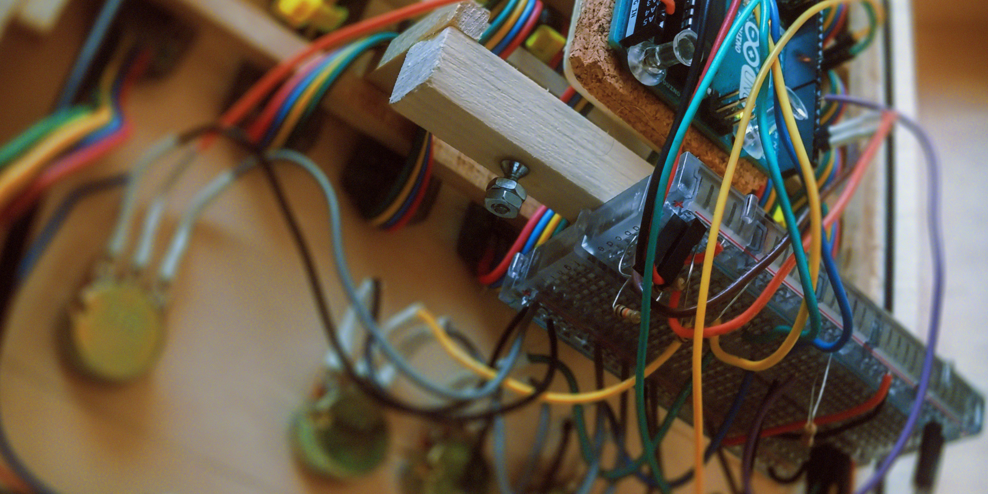
In the case of the CoFoiNo, I built eight or ten various prototypes at different stages along the way, and "prototype" carries a fairly loose definition here. The early "prototypes" were things like the two-piece rig I used to turn on the lights for the first time, just a wire going into a thing; later attempts would be more complex. The picture above shows a pretty rugged prototype, it lasted for weeks; just a simple breadboard-based junction point between all the wires coming off the control surfaces and all the wires getting routed into the Arduino. This was my circuit during the whole, "write some code, see if it works, figure out why it doesn't, repeat" stage of the project, and it's pretty close to the "real" circuit that would ultimately come — with one major exception. When your project is living with an umbilical USB cable, your power is handled for you. Once you're done coding and ready to go out into the big world, you'll need to wrangle your own electrons — and for that, you'll need knowledge.

Complementary knowledge provided below.

Solder is a friendly wire made from metals with a low melting-point. You can unwind a bit of solder, push it onto another metal surface, and use a very hot stick to "flow" melted solder onto the metal. One second later the solder cools and solidifies, leaving a permanent conductive bridge between it and the surface it's on. It's tempting to think of solder in terms of glue, and for all practical considerations that's fair, but where glue merely "holds" a couple of surfaces together, solder becomes molecularly entangled with those surfaces. In fact, as far as electrons are concerned, you've just made one piece of metal out of two — or three, or fifty, or whatever — and this one trick contains all of electronics. You start your electronics build with a bunch of pieces of metal, in the form of wires and components, and you eventually convince electrons that they're all one big piece of metal.

(I'm leaving out some important concepts, by the way. Non-metal semiconductors, electron flow, etc..)

(Actually, just consider this entire explanation a poem. The physics are not actually like this.)

As far as the electrons know, they're exercising free will about which parts they'll go through, based on areas they prefer more than others. This is because electrons don't know about resistors; they look at an area of resistance, groan, and say, "is there another way to the far side of this thing?" If there's not, they'll trudge through the resistor and snap out the other side. If there is — and there's not supposed to be — that's a short circuit, and a swarm of disloyal electrons will nope out of your whole intricate series of reductions and take a shortcut right to the end. The problem with this is that the circuit was expecting you to engage in some basic crowd control, and now it's like The Who are playing tonight.

I apologize for reducing "people being crushed at a The Who concert" to a symbol, but... actually, it presents a morbid alternative to the usual 'flow of water' analogy for electricity. Let's think about it in terms of crowd control and throngs of people; our total available power coming out of the outlet will be the crowd at Disneyland — picture the crowd, picture a deafening mob of insane tourists in mouse-ear caps, all of them desperate for thrills, they're savages — and our little Arduino project will be the maximum occupancy of a boat on the Pinocchio ride. (It's a ride where like ten people get on a boat and are gently floated through a park decorated with miniature houses and stuff. It's the thrill-equivalent of a chinchilla thinking about a hug.) We have to divert enough members of the insatiable horde onto Pinocchio that there's always riders, but not so many that the scene devolves into a nightmare.

In this analogy, "how many people are entering the line" becomes "amps," and "how completely overcome by ravenous insanity they are" becomes "volts." Both numbers are obviously important, and they're important in slightly different ways: if it's not too much of a crowd, we should be okay; if they're not too insane, we should be okay. Just gotta keep keep the crowd and the sanity at the right level.

Resistance is the difficulty of a surmountable obstacle; it's also the third player in Ohm's Law, which states "voltage equals amperage times resistance." In real life, that means you can trade amperage for voltage by adding resistance. In our analogy, that means an unpleasant obstruction in the line — say, a frat guy who snuck alcohol into the park and is now vomiting on people's shoes — will diminish the number of people who stay in line, which is good, but the people who stayed will have been driven much more insane in the process.

Patience diminished. Desperation increased. Voltage rising.

The idea is to control the flow of people onto boats, and there's two ways they can get past you: a large-enough group cramming into the line (cough The Who cough) will just trample you and swamp the boat, or, an insane-enough group will just murder you because they want the hell out of that boat ride. We fail in either case — we fail if there's eleven passengers on the boat, or if there's two passengers on the boat and they're both trying to convince the other that they're Jesus.

That's electricity in a nutshell; avoiding catastrophic crowd behavior. Amps is the headcount, volts is how insane and determined they are, resistance is how you trade a big calm group for a smaller insane one.

With that in mind, let me give you a couple figures and show you a schematic. The socket in my North American wall is putting out around 120 volts — it's spewing determination, pretty much — and for our purposes, we can safely pretend there's infinite amperage.*  The Arduino will want between 9 and 12 volts and at least a quarter of an amp, and the Neopixels have to be considered separately because they'll want exactly 5 volts and they're definitely gonna need an amp or two. We want to run them off of one adapter, so we'll need to accommodate the bigger numbers — find an adapter that puts out 12 volts, rated for loads up to 2 amps — and then manually split off a lower voltage for the Neopixels somewhere inside the circuit.

* Despite the crowd-trampling analogy, amps are generally something your device pulls rather than is-pushed-by. (Volts push, though.) To phrase it in terms of the analogy, tramplings are very rare and insane people are a constant problem. Actually, that's probably just true in general.

We'll come back to the special-needs dual-voltage power supply issue later, because that's a whole separate conversation; for now let's pretend like it doesn't exist. Let's pretend that we're actually surprise heirs to a forgotten family fortune, and that our bed will be full of puppies tonight, and that an Arduino and a bunch of Neopixels can share a power supply. Reality thusly suspended, take a look at this schematic.


http://www.friendsinyourhead.com/arduino/031.jpg


This is what the Pinocchio ride looks like.

That's our power supply, in the top left. (Entrance to the line.) The schematic symbol for a DC power supply is a few pairs of vertical lines with a taller line and a shorter line in each pair; thus the symbol has a tall line on one side and a short line on the other, with the tall side being positive and the short side being negative-slash-ground. (Ground would be the far end of the ride, where people get off having gotten what they came for.) The symbol for ground is a vertical line dropping into a horizontal line and dissipating, which represents... the... ground, I'm guessing. Art. Whatever.

You can see that there is one big blue ground being shared throughout the entire project — this is true of all circuits, you always want everything to share a common ground. You can think of it in terms of a gutter; you're adjusting power all over the place, and after every adjustment it's either getting read by another part of the circuit or going into the gutter. I've left out "return" arrows coming back up the ground wire to the power supply, but you could picture it that way if you wanted to. You can also see the big red line — which is our power, call it 12 volts coming out of a "brick"-style wall adapter — and the first thing that happens to it, which is that it arrives at the giant comedy-sized toggle switch.

The symbol for a switch is pretty sensible, it looks a wire with a door swinging out of it; the idea being, close the door, close the switch, close the circuit — connect the wire. When the toggle switch is open, the actual physical connection inside the switch is broken, the wires are separated by air and the power doesn't go anywhere. (Another way of thinking of it is that the air has infinite resistance, which could be an infinite number of vomiting frat guys holding up the line, or, like, a sign that says "go away.") When the switch is connected, the power moves on through the circuit.

The Arduino and the Neopixels are both getting their power straight from the source, in the form of the solid red line. The Arduino uses some of that power to do its Arduino-ing, of course, and the rest to power the peripherals it's attached to. What's nice about this is that once you've powered an Arduino, at somewhere between 9 and 12 volts, the Arduino will turn around and provide you with a safe 5-volt source — represented by a dotted orange line in the schematic — that you can use for measuring the throughput of knobs and buttons and whatever other voltage-measurement devices you're using, and you can be assured that you're not gonna blow the Arduino out of the water with more voltage than it can handle.

With the nice 5-volt power source from the Arduino, we set up a couple of "rails" — that is, an open canal of power, an open gutter of ground — and just tap into them for our control surfaces as necessary. This amounts to a parallel circuit, where every little device is drawing from the same big pipe as equals, instead of one device getting first dibs on the power and passing along the leftovers.

The CoFoiNo has five controls; four knobs ("that's potentiometer to you, kid") and a button ("momentary push-button switch, please, I didn't go to school for eight years to be called a 'button'"). You'll recognize the symbol for the button as being the same symbol we used for the toggle switch; the symbol for a potentiometer is actually the same symbol you'd use for a resistor — wire going into one side of a box and out the other — with an extra slant-y line on top of it, to indicate that it's variable. As far as our circuit here is concerned, the button and knobs are all almost exactly the same thing: power goes in one side, is adjusted by the user, and delivered to the Arduino in a thusly-chosen state. The button is an all-the-way-on or all-the-way-off signal that comes in at 5 volts; the four knobs all return a variable voltage between 5 volts and 0 volts depending on how twisted they are.

(Heh — "twisted." Synonym of "insane." The system works, people!)

Arduino provides some power, power goes into the button, power is sent back to the Arduino by pushing the button. The Arduino is measuring the button voltage digitally, which is to say it's only accepting "on" or "off" answers on the button front. The power also goes into the knobs, whereupon some amount of it is getting shaved off and immediately sent to ground, and the remainder is sent back to the Arduino. The Arduino is measuring the knob voltage analog-ly, which is Arduino-ese for "instead of two states, 'on' or 'off,' we'll say there's 1,024 states of 'on-ness' to 'off-ness' and round to the nearest one." It's comparing the voltage coming in — 2.5 volts? 0.8 volts? 4.6 volts? — to the voltage that it provides — 5 volts — and taking note of the fraction.

Once the Arduino has that information — is the button being pressed? how much red-green-and-blue is the user asking for? where does the user want the selected column to be? — it can fill in the variables in the Connect Four program, so it's ready to go. (It's worth mentioning that we only need to know the R-G-B knob values during the "pick a color" stage, so those particular variables spend a lot of time not-mattering.) The program does its clever work of taking the user inputs and re-arranging them into a meaningful series of grid-based pixel commands, and it sends those commands into the Neopixels.

The user inputs are all handled by the Arduino reading incoming voltages; the Neopixel commands are all sent by the Arduino writing voltages. We don't actually have to know how that happens for us to program it — the specific digital voltage timing that tells the Neopixels what to do is all handled by a software library that was written for use with Neopixels, so we can just say "pixel 5, red 255, green 0, blue 0" or whatever and the library converts that into a series of impossibly-fast voltage pulses that the Neopixels understand — all we have to do is hook up the last two Neopixel wires to the Arduino.

And, guess what?


You flip the toggle switch and the game works.


http://www.friendsinyourhead.com/arduino/060.jpg


In theory, anyway.


Can Teague stretch the rogue wave cliffhanger past its breaking point?
Will we get to see the actual circuit on an actual board?
Is this going to be the longest document ever written?

Stay tuned

Teague Chrystie

I have a tendency to fix your typos.

Thumbs up +1 Thumbs down

Re: "Radiopunk" // In Which Teague Uses This Forum As A Notebook

Building a permanent circuit is wonderful. You put on some tunes, study your schematic, look at a million photos of your prototype, grab a circuit board and start throwing components together. You can translate the perfect circuit drawn on your schematic into whatever kind of criss-crossed mess you want on your circuit board — the schematic demonstrates how the bits connect to each other, that's all — and you can do it with confidence, because the old prototype worked and the schematic is just a map of the old prototype.

What of mistakes? For example, maybe everything is beautifully laid out on the board and soldered together, but you forgot to connect the ground on one side of the circuit to the ground on the other and now nothing works because half of the circuit doesn't have a connection to ground. (This is just a made-up example; I definitely didn't make this exact mistake two different times.) That right there is a massive infrastructural failure, it's a catastrophe — and yet, hack something together Apollo 13-style by soldering a stray wire from one side to the other, and it's permanently fixed. "That'll do, immortal hack. That'll do."

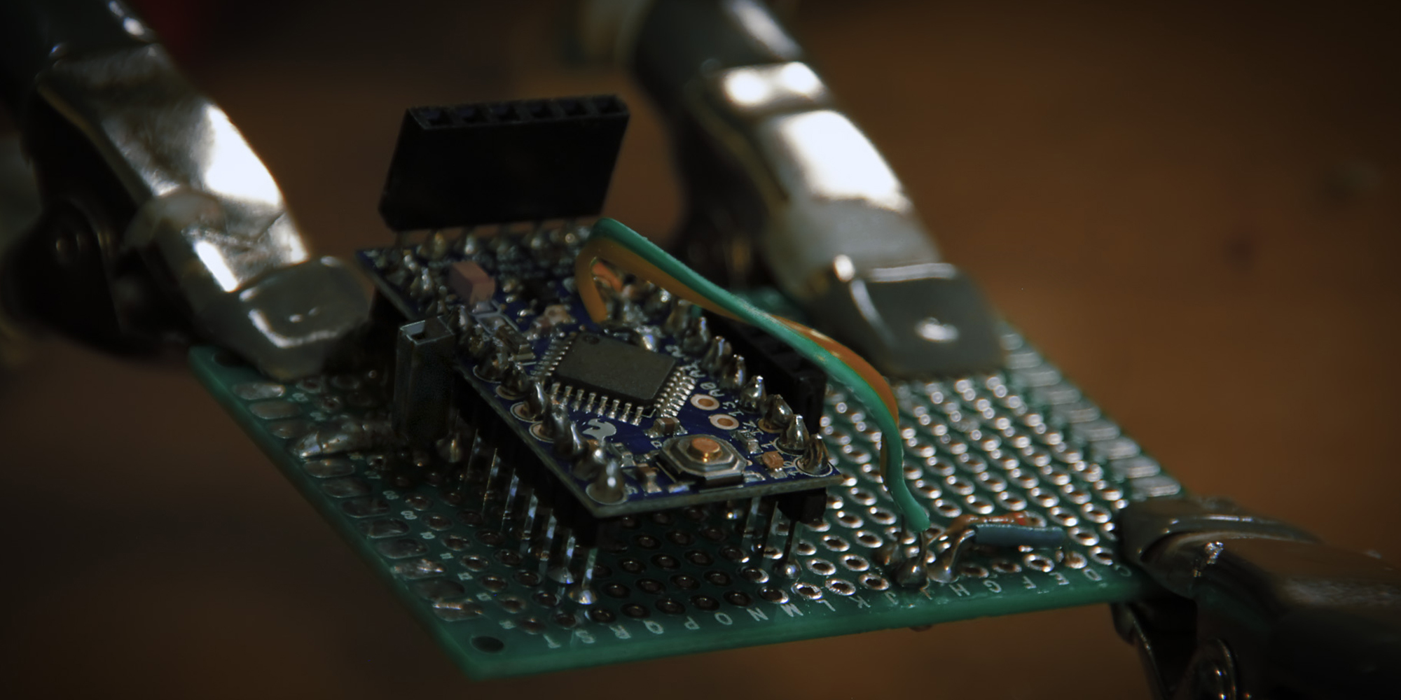
There's a dozen or so "official" Arduino boards to choose from, and hundreds of third-party boards that are just as good. An Arduino Pro, for instance, is pretty much a flat Arduino Uno; where the Arduino Uno's I/O pins are big breadboard-y slots for sliding wires into, the Pro's I/O pins are tiny solderable rings along the edge, making for a much-sleeker permanent installation. The board I used in my CoFoiNo project is an Arduino Pro Mini — it costs ten bucks, packs as much wallop as an Uno, and is roughly the size of your Enter key.

To build a CoFoiNo board, step one is to grab some headers and throw an Arduino Pro Mini onto 'em.

http://www.friendsinyourhead.com/arduino/121.jpg

A "header" is a plastic fence with metal pickets, serving up evenly-spaced wires quickly; they come in long rows of thirty or so, and you snip them down to fit. For my CoFoiNo, two male headers were trimmed into units of 12 and soldered under the Pro Mini's belly like centipede legs.

After that, a female header was trimmed down to a unit of 6 and soldered atop the Pro Mini's talkin' head.

http://www.friendsinyourhead.com/arduino/130.jpg

(One of the compromises a Pro Mini makes for size is doing away with the traditional USB jack, replacing it with still more solderable rings; you provide the USB-to-wires breakout yourself and make wires touch rings however you please. I like to do this by soldering a female header directly onto the terminals; that way I can connect and disconnect my USB cable all willy-nilly-like and just remove the header when I'm done.)

Thusly outfitted with limbs, my Arduino bug was soldered into position on a brand new piece of perf.

http://www.friendsinyourhead.com/arduino/150.jpg

Most of the circuit is straightforward — like, "wire goes from button to Arduino with nuthin' in between" straightforward — but there were a few details that needed to be sorted out, so I handled them first.

There was the matter of how to connect the Neopixels to the circuit. I decided the solution to that was "more headers" — male headers on the board, female headers on the NeoPixel cable. Not only does this look clean, but you'll recall that such configurations also allow for a great deal of willy-nillyness, which is next to godliness.

http://www.friendsinyourhead.com/arduino/160.jpg

This would require running a wire to each of the four Neopixel header pins from their various places of origin. I'd handle the red and blue wires of power and ground later; I hooked up clock's green wire and data's yellow wire to the Arduino and ran them over to a staging area across the circuit board. This gave me a little room to install another detail, a little 330 ohm resistor — orange-orange-brown, if you're playin' the home game — on the data line between the Arduino and the Neopixels. Adding that resistor is one of the things they tell you to do with Neopixels when you buy 'em — put a resistor across the data line, put a big capacitor between power and ground. Easy peasy.

http://www.friendsinyourhead.com/arduino/170.jpg

This is one of the pleasant rhythms of building circuitry. Pick component, poke through circuit board, solder to pads, snip-off excess — pick wire, cut to fit, solder to pads, snip-off excess. Metallurgical sewing.

http://www.friendsinyourhead.com/arduino/180-2.jpg

While I was fiddling around with headers, I also went ahead and installed a single female header next to the Arduino terminal where my button would go. Installing a single header is pretty weird; this is one of those things where you could ask me why I went that way with it and I'd say the answer was "it felt right," when it would really be "it's fun to snap things in half with cutters and no header can escape me."

Button wire goes into header, header goes into Arduino terminal. Done.

Well, almost. There's one more connection the button wire needs to make, and the reason why is neat.

You'll recall that charge passes through the button into a wire on the far side that the Arduino measures, and that the Arduino will declare it all-the-way charged or all-the-way grounded — such is the nature of a digital measurement; it must declare the terminal "on" or "off" because those are the only two words in binary. When you let charge through the button, the Arduino has a pretty easy time looking at that wire and declaring it charged; the trick is, when you aren't pressing the button, the Arduino is still measuring the wire... and what does it see? Noise, almost certainly. Little variations of voltage weirdness which are either getting picked up inductively or because you're a bad person.

There's a solution to this problem, and the solution brings a problem with it. The solution is to connect your button output to ground, so the fluttery "off" charges get sucked out before they make it to the Arduino. The problem with that solution is that your big "on" charge gets sucked out too, because there is nothing an electric charge likes more than ground. Charge becomes like a puppy when it sees ground; give charge an equal choice between ground and anything else, it'll choose ground every time.

Of course, the key word there is "equal," and that's a condition you can fiddle with.

One thing to keep in mind is that the charge kind of sees the Arduino as ground, too; it's just ground with some stuff in the way. (This is why the Arduino is measuring noise, after all: stray charges in the wire are getting pulled through the Arduino because they have no place else to go.) As such, there are really two paths to ground at work; a "main" path and an "Arduino" path. You want the button signal to take the Arduino path, but it won't, because it's not the path of least resistance.

Any ideas for how to solve this problem?

http://www.friendsinyourhead.com/arduino/181.jpg

Boink.

The header is still connected to the button's Arduino terminal, and now also to ground through a resistor.

That-there solution is called a "pull-down" resistor, and you start to see it everywhere once you understand why it works. We want to keep the strong "on" signal when it gets pushed through, but lose the weak noise signals that are always there — so, what we do is make a hurdle the strong signals can clear and the weak signals can't.

When the button isn't being pressed, the fluttery noise on that wire is sucked ("pulled-down") to ground, because that path — resistor included — is still less-resistant than the one through the Arduino. The line goes quiet; Arduino declares it "off." When the button is pressed, the charge on the wire is suddenly strong enough that the Arduino declares it "on," even with a bit of the charge being lost to the other path.

The pull-down resistor; it de-bounces jittery switches and quiets the dull roar of false positives. You can also have "pull-up" resistors do the same thing for false-negatives, usually on a line that's meant to be "on" except for when it's off. The actual value of the resistors will vary depending on how much bias you need; I opted for overkill and a thousand-ohm resistor. (That's brown-black-red, home-gamers.)

By the way, if you meet a thousand-ohm resistor, he will absolutely insist that "thousand-ohm resistor" is his dad's name and that you should call him "1k." Kind of a try-hard, this guy. Whatever. Let him have it.

http://www.friendsinyourhead.com/arduino/240.jpg

After my distracted swerve through Button Corridor, I clipped a quartet of male headers and hung 'em out in Neopixel Country. The green and yellow wires were soldered to the first and second headers, with the third and fourth headers getting new wires in black and red for ground and power. I soldered each to their respective headers, then spent a minute making a pretty little ninety-degree bends in the wires where they'd reach over and connect to the Arduino.

"Is that important?", you ask. "Putting pretty little bends in the wires?"

"There has literally never," I begin, "been anything more important," I continue, "than putting pretty little bends," I add without blinking, "into these wires."

You wonder why you asked. I wonder too.

http://www.friendsinyourhead.com/arduino/250.jpg

I soldered my inarguably-valuable bends to the Arduino's ground and outgoing-power terminals, and the insular little world of perfboard inhabitants was complete. It was time to hook up the box.

I cracked it open and wired all the power components in the walls, starting at the bottom left with my "barrel jack" for plugging a power brick into; I put a big 'ol capacitor across it, just like the Neopixels asked for, and taped it down with one-and-a-half miles of electrical tape. The cap-coupled power supply sends juice into my giant comedy-sized toggle switch, which in turn sends juice into a voltage regulator that blends it up and serves it cold at a refreshing 5 volts. I left the wires of my unfinished power supply a-danglin' and moved on to my control surfaces.

http://www.friendsinyourhead.com/arduino/200.jpg

I made a rail of red wire and hooked it to the supply side of all five components, then a ground rail in black to share between the four potentiometers. (The button doesn't get a ground connection, because whatever goes into the button comes out at the Arduino.) The power rail would ultimately be connected to the Arduino's voltage output, so it was left alone for the time being; meanwhile, the ground rail was connected directly to the barrel jack.

There's a few ways to mount a circuit board onto your project; for one thing, they come with nice big holes at the corners that you can push a screw through, so that opens up a world of possibilities. In the case of the CoFoiNo, I mounted my board onto a plastic box with matching dimensions — a random lucky find — and stuck it to the CoFoiNo with a little help from my friend "all the hot glue in the world."

http://www.friendsinyourhead.com/arduino/265.jpg

Here's the thing about hot glue: it's only cheap-looking if you can see it. Find something to put it under.

Once I had the circuit board on the CoFoiNo, I was able to connect all the power thingies to the grid. I used the previously-danglin' wires from my power supply to bring power and ground to the Neopixel headers, whereupon they also get split off and carried to the Arduino in wires with pretty ninety-degree bends.

I made myself a Neopixel-lookin' extension cord and popped a female header onto the end of it; the other end was soldered directly to the Neopixels cable. I plugged my newly-finished Neopixel cable onto the circuit board headers; the willy-nillyness was immediate and intense. The circuit was almost complete.

http://www.friendsinyourhead.com/arduino/280.jpg

The last bit of circuitry was also the simplest, really — signal wires were soldered to each of the five player controls. Each of the controls already had its power hookup, all that was left to do was connect the output back to the Arduino.

http://www.friendsinyourhead.com/arduino/290.jpg

http://www.friendsinyourhead.com/arduino/300.jpg

http://www.friendsinyourhead.com/arduino/310.jpg

(There's also a nifty GIF that shows the completed circuit turning around in a circle, but it's ten megs and I didn't want to embed it like the other images.)

Building a permanent circuit is wonderful, and it's even fun for folks who don't know what they're doing — I taught my girlfriend to solder and ten minutes later she was assembling a kit. (By choice, I mean. She wanted to. Stop looking at me like that.) If you're feeling the itch and don't know where to start, there's no shortage of kits available that come complete with all the necessary components, plus a circuit board with the schematic laid out on top of it and printed instructions. (You'll need to grab a soldering iron and little thing of 60/40 solder, though, both of which can be found online or in the tool section of most hardware stores — also, learning to solder requires five minutes and Youtube.)

This gargantuan essay is still not quite done, of course; the moment of truth is yet to come. What happens when you take a whim, add three months, plug it directly into the wall and flip the switch?


Will... fire? Just, fire? Will it fire?

Seriously, does it catch fire?


Stay tuned

Teague Chrystie

I have a tendency to fix your typos.

Thumbs up +4 Thumbs down

Re: "Radiopunk" // In Which Teague Uses This Forum As A Notebook

This is the best thing I will consume this week.

(UTC-06:00) Central Time (US & Canada)

Thumbs up Thumbs down

Re: "Radiopunk" // In Which Teague Uses This Forum As A Notebook

"It doesn't work" is what happens, because you messed something up and you'll have to troubleshoot for a while until you figure it out — after which point it still doesn't work, because you messed something else up and you'll need to troubleshoot for a while until you figure it out, and so on. You won't know when it's going to be fixed, you won't know if you're fixing it; all you'll know is that you're trapped in a nightmare of indeterminate breadth and that your moment of truth is somewhere on the far side. Don't get thrown off. Troubleshooting is how the universe tests grit. This is the very last fight, it's a war of attrition; the only way through it is to protect your ambition from your mood, focus on the problem in front of you, and proceed from each devastatingly stupid puzzle by saying "thank you, universe, may I have another?"

I troubleshooted a thing, flipped the switch to check it, and suddenly the CoFoiNo was complete.

One moment you'll be in the weeds, the next moment you'll be completely done with the project.

http://www.friendsinyourhead.com/arduino/012.jpg


http://www.friendsinyourhead.com/arduino/027.jpg

Which isn't great for dramatic pacing.

In a good story you'll find a clear path leading to a primary obstacle and an ultimate moment of success or failure; in reality, things aren't so pat. The first time I switched on the CoFoiNo and it worked was special, of course — it was also underwhelming. The way it goes in real life is that the ultimate moment of truth is just finding out that all the smaller moments of truth are done happening now. By the time I hit the switch, I'd already had my moment of truth with the circuit, because there had been a prototype before it; I'd already had my moment of truth with the program, because I got it working on the computer; I'd already had my moment of truth with the box, because the box was finished. For being the first time in history that flipping the switch did anything at all, what it did was pretty familiar.

That's how it goes — you look for one thing in a story, but reality gives you another. The ideal telling of this story would end with an ultimate moment of truth, because an ultimate moment of truth is what we're waiting for when we listen to a story. Unfortunately, we arrive at the end of the project, and the reality of that moment didn't feel like a moment of truth so much as a moment of "what's next?"

Not only is "what's next?" not the ending I'd hope for in a story; it's actually the same emotional beat I started the story on. I didn't know what to do with myself at the beginning of the story, and I didn't know what to do with myself at the end of it. Not much of an arc, when you look at it that way.

What's funny is that this project does contain an ultimate moment of truth, which I stomped all over by starting the story the way I did. The moment of truth in the CoFoiNo story is the first thing that happens in it; I follow Paul's advice and dive headfirst into completely foreign waters. The moment of truth is deciding to try.

In the early months of 2015, I decided to stop doing pretty much everything I had been doing up until that point — certainly to stop thinking the way I had been thinking up until that point — and unplug everything.

Then, I did something new and plugged it in.


Epilogue


Arduino wasn't the only new addition to my life in those early months of sudden focus; there was also lettering, club-juggling, bass guitar, bicycling, classical music, and a whole slew of unrelated books about how the world works, ranging from rare earth metals to string theory to grammar to the FCC. The buzzing in my head where the internet used to be — yeah, that took a few things to tamp down, not just the one.

But I did silence the buzzing in my head, and I did get electrons to dance for my amusement, and I did learn the way to shore by jumping off of the boat. The stupid plan worked. For this I thank the modern American philosopher Christopher Walken, who has said, "if you want to know how to build a house, build a house; don't ask anybody, just build a house" — and who presumably said it in a Christopher Walken voice.

It's been a year now since I sat down with a dollar-store notebook and started copying schematic symbols, and since then I've finished not only the CoFoiNo, but also a miniature one called "CoFoiNo Micro," plus a handful of synthesizers and musical instruments, and Rick and Morty props, and toys, and experiments, and just followed up on more whims than I can recount here. Ideas that randomly occurred to me as a thing that might work if you knew how to build 'em, whereupon it also occurred to me that I did know how to build them. The visions of power that descended upon me when Paul first explained what Arduino was; whims like these are how that power manifests itself.

Whim example: I made a guitar tuner that works by blinking an LED at the same rate as the tuned string should vibrate, so you can tune each string by watching it vibrate under the blinking light and tightening the string until it stands still, mid-vibration, perfectly in sync with the blinking. Occurred to me, thought it would, built a prototype, totally worked. Second whim example: I made a spectacularly dorky wearable device called the Fantasia Engine (a name brought to you by the same underappreciated visionary responsible for the word "radiopunk") that creates a lightshow in front of your eyes in time with whatever music you're listening to, either automatically by doing a live spectrum analysis of the audio, or manually by measuring "conducting" gestures you make with your hand and converting them into a three-dimensional color picker.

Also, if you easily grasped that I could use Arduino to realize those whims — congratulations, you now have Arduino-vision. I'll bet bugging a litter-box with a breathalyzer doesn't sound so crazy anymore, does it?


...fine.


Teague Chrystie
2016

Teague Chrystie

I have a tendency to fix your typos.

Thumbs up Thumbs down

Re: "Radiopunk" // In Which Teague Uses This Forum As A Notebook

Alrighty, so that's the rough draft completed. Now I'm gonna go back through it with a fine-toothed comb and make it into a single essay, which will hopefully involve making it considerably better as concepts are tied together throughout. I'll post the "director's cut" of the finished essay here and in the first post, and send the manuscript off to the electronics company for them to chop it down to whatever size they want.

EDIT: Just got the rough draft into a word processor for the first time; comes in at just shy of 12,000 words.

In the meantime, here's a thing to look at.

Teague Chrystie

I have a tendency to fix your typos.

Thumbs up +7 Thumbs down

Re: "Radiopunk" // In Which Teague Uses This Forum As A Notebook

That's amazing! Seriously good job! I wince at the thought of the code though being that I'm struggling my way through getting to grips of code writing myself. I absolutely love the esthetics. Makes a want to build in more complexity to my first Arduino/aka Macro-key-no (the name is being work shopped) first project - a USB macro-key box with ten macro keys and a switch to change between programmed profiles. Ten macro keys as dictated by the size of the hobby box that was literally pennies. But starting off, as proof of concept it should do well. I haven't settled on how exactly it's gonna work. Be it pull-up switches, a pull-down resister ladder or some sort of array. A bunch of fiddling with a bread board me thinks. I'm just waiting on a heap of things to ship from China. Cherry MX Blue swiches are the only thing to arrive so far.
http://s9.postimg.org/l7mkeo4an/Picture_17.jpg

Side note you hand drawn sketched diagram is a work of art in itself. I think I'll just stick to Fritzing (too much work for me).

I can't figure out what the springs are for?!

Last edited by Regan (2016-04-16 20:46:50)

The difficult second album Regan

Thumbs up Thumbs down

Re: "Radiopunk" // In Which Teague Uses This Forum As A Notebook

I am in absolute awe.

Eddie Doty

Thumbs up Thumbs down

Re: "Radiopunk" // In Which Teague Uses This Forum As A Notebook

http://38.media.tumblr.com/d2d97e94e4b5bd5d9334cf2f85f88ddf/tumblr_n8tqcqPhPB1thowlgo1_250.gif

What an inspiring write-up for such an inspiring endeavor. The motorized time lapse slider I've been tinkering on for over a year now is starting to take form, and this is thread is a bunsen burner under my chair. Thank you for this.

Thumbs up Thumbs down

Re: "Radiopunk" // In Which Teague Uses This Forum As A Notebook

*collapses*

Here's the whole thing in essay form. This took so goddamned long. My god.

It's changed quite a bit from the rough draft, but it's obviously similar, so you might not get anything new out of it if you've already read it. I'm gonna sit on it for a day or two before sending it off to the guy, I think.

Teague Chrystie

I have a tendency to fix your typos.

Thumbs up +1 Thumbs down

Re: "Radiopunk" // In Which Teague Uses This Forum As A Notebook

Across the seeeeeeeeeeeeeeeeeaaa!
A PALE MOON RISES!
The ships have come to carry you HOOOOOOOOOOOOOOME!

And all will turn to silver glass.
A light on the water, grey ships pass into the WEEEEEEEEEEEEEEEEEEEEST!

Witness me!

Thumbs up Thumbs down

Re: "Radiopunk" // In Which Teague Uses This Forum As A Notebook

Teague wrote:

*collapses*

Here's the whole thing in essay form. This took so goddamned long. My god.

It's changed quite a bit from the rough draft, but it's obviously similar, so you might not get anything new out of it if you've already read it. I'm gonna sit on it for a day or two before sending it off to the guy, I think.


Absolutely fantastic! Great bit of writing. Informative to boot.

The difficult second album Regan

Thumbs up Thumbs down

Re: "Radiopunk" // In Which Teague Uses This Forum As A Notebook

Both the essay and an "audiobook" version (which is a stretch, seeing as it's only an hour long) are now up.

http://www.friendsinyourhead.com/arduino/radiopunk-web-black.jpg
So, that's a wrap. Woot!

Teague Chrystie

I have a tendency to fix your typos.

Thumbs up +4 Thumbs down

Re: "Radiopunk" // In Which Teague Uses This Forum As A Notebook

FUCK YES AUDIOBOOK


(insert lower-case letters here since I can't do all-caps posts apparently)

Thumbs up +1 Thumbs down

Re: "Radiopunk" // In Which Teague Uses This Forum As A Notebook

I am at once pleased and saddened by such a thoughtful policy and its subsequent stomping of free expression.

Teague Chrystie

I have a tendency to fix your typos.

Thumbs up +1 Thumbs down

Re: "Radiopunk" // In Which Teague Uses This Forum As A Notebook

What is this country coming to, I ask you, when a man can't express himself at the proper metaphorical volume on an internet forum? This is how the Roman empire fell.

Thumbs up Thumbs down

Re: "Radiopunk" // In Which Teague Uses This Forum As A Notebook

YAAAAAAAAAAA! l'M EXCITED!

Witness me!

Thumbs up Thumbs down

Re: "Radiopunk" // In Which Teague Uses This Forum As A Notebook

I finally got a chance to listen to this. Well done, sir. Aside from some audio issues, this was great. And the content itself was funny and inspiring.

Witness me!

Thumbs up Thumbs down

Re: "Radiopunk" // In Which Teague Uses This Forum As A Notebook

Thanks.

What were the audio issues, though? I wanna hammer that shit out if it's a thing.

Teague Chrystie

I have a tendency to fix your typos.

Thumbs up Thumbs down

Re: "Radiopunk" // In Which Teague Uses This Forum As A Notebook

Your plosives were a little harsh in the first few minutes of the track. They seemed to clean up after a while but that may have been my ears getting used to it. It wasn't bad, really, just a tad on the distracting side.

Witness me!

Thumbs up Thumbs down

Re: "Radiopunk" // In Which Teague Uses This Forum As A Notebook

Hey Teague, is the Radiopunk address accessible to members only?
Mind if I link Dale Daugherty to it?

(UTC-06:00) Central Time (US & Canada)

Thumbs up Thumbs down

Re: "Radiopunk" // In Which Teague Uses This Forum As A Notebook

Nope, friendsinyourhead.com/arduino/radiopunk is just fine for sharin.'

tinyurl.com/radiopunk points to the same thing.

Teague Chrystie

I have a tendency to fix your typos.

Thumbs up +1 Thumbs down

Re: "Radiopunk" // In Which Teague Uses This Forum As A Notebook

I was just goin' through my old unlisted YouTube uploads, and I stumbled upon a bunch of work-in-progress videos from my CoFoiNo stuff. (We're currently midway through the two-year anniversary of all this, it turns out.)

Anyway, I would never make these videos 'public' — I mean, unless you already care, this is some dry-ass content, let me tell you — but I don't have any particular reason to keep it 'private,' either.

I make no promises about their entertainment value; hope abandon all ye who enter here. Enjoy.

June 28, 2015

June 29, 2015

July 13, 2015

July 14, 2015

August 19, 2015

August 21, 2017

EDIT: Not that I even think anybody will give a crap about these clips, but; if anyone's interested, I seem to have a shitload of similar videos from plenty of other electronics builds along the way, most of which never got much further than the clip I recorded. I regret not finishing some of those, but I'm happy with my habit of documentation, at least.  smile

Teague Chrystie

I have a tendency to fix your typos.
Thumbs up +1 Thumbs down